
By Paul McMahon VK3DIP
First of all this article is not the only way to make printed circuit boards, it is simply one way I have found to work well for me to make one off boards for my own use. There are lots of techniques to do this out there with infinite variations of software tools, media, chemicals, milling machines, and the like. If the technique here doesn’t work for you then my advice is to just keep experimenting until you find something that does, it’s out there somewhere.
The first step is to draw the board. In my case I use a PC with a general purpose drawing package simply because I happen to be familiar with it. Many people use specific PCB software packages for this, or even just draw it by hand. In my case the drawing is just black on white with the black representing the copper tracks. The only trick is that, because of the way this image will end up being transferred to the board, you have to draw it as a mirror image. That is what you draw will be what you would see if you could be looking through the top of the board down to the copper tracks on the bottom, rather than what it would look like if you look directly at the bottom of the final board.
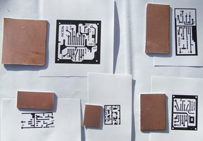
This is an example of a board I recently did. Note the text is mirror image.
Some people find it easier to draw the board the normal way around and then just flip it in software. In my case I have found it simpler to just think that I am looking through the board.
In this method the printing is the key, it requires either a reasonable quality laser printer or some other printer and a photocopier. The bottom line is that the final printed image must be produced by a machine that uses thermal toner and not ink. The basic idea of this method is that toner is basically black stuff that is sticky when hot and when cool is impervious to water and the chemicals used to etch the unwanted copper. The printed image is placed on the bare copper, toner side in contact with the copper and then heated, the toner then sticks it to the copper. The idea is to then remove the original backing leaving the toner stuck to the board. So this method belongs to the “iron on” family of methods which includes the “press and peel” film available from places like Jaycar. In my case I found that while the special film worked well most of the time, it was very expensive. So in looking for alternatives I came across references to people using just plain paper. In my case I had no luck with this with the small fibres on the paper surface usually doing a much better job of holding on to the toner than the smooth copper. What I have ended up using is called coated matt surface inkjet photo paper. Now having stressed that the image must use toner, don’t be confused when I say that the paper that is used is intended for inkjet printers. In this case the paper is basically normal paper that has had one or both sides coated with a thin layer of usually a chalk based stuff. The idea in inkjet printing is that this gives a very smooth white surface but one that the ink can still soak into. In our case here the chalk layer is not effected by the heat of the laser printer process and the toner doesn’t end up bonded to the paper just the chalk layer.
So in my case I buy the paper from computer swap meets and I can get it for about $12 for 100 sheets. So long as the words on the package say something about coated, and matt, it is worth a try. If you do buy one sided coated paper, and this is the cheapest, check to make sure you can tell which side the coating is on because you need to be able to do this to ensure you are printing on the correct side. If you don’t do swap meets, I have also found that Officeworks has its own brand matt coated photo paper which works well.
You may have to practice a couple of times with your particular printer/photocopier to figure out which side of the paper it prints on (important when you use one sided paper) and to get the image at the correct size. Also if you have options in the printer driver making the image a bit darker and turning (for just PCB’s printing only) any toner saving feature off helps. The ideal print for a PCB transfer is one where, when you run your fingers over it, you can feel the slight raised bump of the black.
I tend to print several boards images on a single sheet of paper even if I only need one even though the paper is reasonably cheap. Occasionally I may have to try a couple of times to get the iron on to work well enough, especially if I have skimped on the next stage of cleaning the board, and it is nicer not to have to go back and print another page. Note that you need to leave a reasonable margin of unused paper around each image as this will be used to secure the paper to the board while ironing.
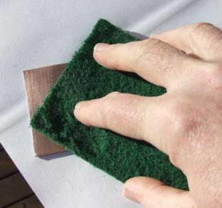
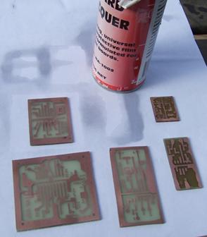
The next step is to prepare the blank PCB. This involves both cutting to size and more importantly cleaning the surface. Surface cleaning is probably a bit of a misnomer; the aim is to not only make the surface bright copper which will help rapid etching, but to also slightly score the surface with very fine scratches to give the toner something to hang on to. Cleaning is also needed to remove any traces of oil from the board which would also cause the toner not to stick. The best method I have found to do this is to use a clean green scritchy thing as sold for kitchen duty. Don’t get the cheap ones, don’t get the ones that say kind to dishes, don’t use one that has already been used in the kitchen as it will have traces of oil in it, and don’t put it back in the kitchen when you have finished if you value domestic harmony. The idea here is to actually minutely scratch the surface of the copper. If you are cleaning the board after a failed attempt you will also find that moistening the scritchy with a small amount of methylated spirits helps.
You will also note from the photos below I tend to do several small boards at once as the etchant I use doesn’t keep once made up. The photos also give you an idea of how much white space to allow.
The first step is to cut out the toner images. You will have seen in some of the photos above the idea is to leave a reasonable amount of unused white space around each image as this will be wrapped around the sides of the cut out boards. In my case after cutting out I put the printed picture toner side up on a flat surface, and then place the cut out board copper side down so as to cover the toner image. The sides of the paper can now be folded up over the back of the board to make a little parcel that, when turned over and pressed flat, will hold the paper firmly in place on the board. Do not use tape or similar to hold the paper down, this will melt when you iron it and will stick to the iron and not promote domestic harmony. Apart from being relatively cheap, some of the good things about using a paper rather than a special plastic film are that it is not as critical of iron temperature and is more robust so you do not have to be quite as gentle. I have found that the simplest settings on the iron to use are temperature all the way up, steam off, and press as hard as you can but only with the flat of the iron, don’t use the point as this will cause the paper to rip. Try and press down not shear as this may cause the paper to move relative to the board.
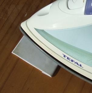
You will also see from the photo’s that this needs to be done on a hard flat surface such as a plank of bare dressed wood that doesn’t mind getting hot, do not use the family ironing board ( domestic harmony issues) . You may have to experiment a bit to find a combination of iron temperature and pressure that works for you. The ideal case, which one of my friends uses, is a set of rollers and fuser (heater) from a junked photocopier which provides just the right pressure and fusing temperature to suit the particular toner. In my case temperature flat out and press hard for about 10 seconds works. It is too hot if the paper starts to brown, if you press too hard you risk tearing the paper or smearing it. I turn the steam off, not because it would hurt the board, but because the wet paper tears more easily than dry.
Having ironed the board put it aside to cool down. When cooled you may notice a few small areas on the back of the paper which look like bubbles this is actually where the paper has not had toner to stick it to the board so unless it is in a spot where you know there should be toner don’t worry about it.
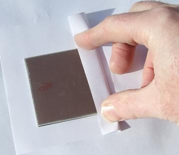
The paper backing should now be removed, but unlike the special films you can’t just peel the paper off you need to rub it off. Do this by wetting the paper with water and letting it soak in. then using a rubbing motion of the thumb while pressing on the paper rub it until the paper starts to pill and come to bits.
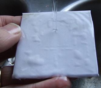
You will see in the photos that when wet the bubbles in the paper where there is no toner become very evident so you will quickly get an idea if your toner is sticking. As necessary keep wetting the paper so as not to be rubbing dry. Keep rubbing until you have removed all the paper just leaving the toner hopefully stuck firmly to the board.
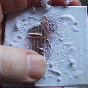
You may find some areas where the toner has not stuck down well, this may be due to uneven pressure, or not enough heat, but most likely it will be down to insufficient cleaning. So clean the board off, the green scritchy and metho are your friend, and try again until you get one that is close enough. Small touch ups are always necessary even with the best of processes. Note for various reasons usually to do with the way your printer uses toner the areas that will give the most problems are large solid black areas around the edges, fine lines etc. usually work pretty much perfectly. Luckily the larger areas are the easiest to touch up so. Problems with very fine lines and text etc. tend to be mainly at the etching stage.
The rubbed off board is left to dry, and as it dries you will notice the black develops a white coat, this is the coating from the paper and is not a problem except if it is filling in the small holes in pads, so if you see signs of this a drop of water and another rub will fix it.
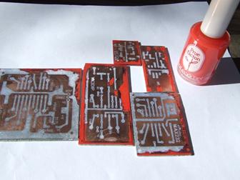
The simplest way I have found to touch up areas where the toner has not stuck is to use nail polish. This is good because it dries quickly, comes in a nice small bottle with its own brush, and if bought at a discount store is quite cheap. Do not borrow it (domestic harmony again) just pick some awful shade that no one would wear and explain carefully what its use will be to avoid misunderstandings.
It is possible to trim the supplied brush to a point to do finer work, but I find that if you go a bit over or make a mistake somewhere, you just wait for it to dry then carefully using a pin or similar scratch off the unwanted bits. This leaves a straighter edge. The boards are left to be fully dry, and if double sided PCB is used where one side is to be an earth plane, I use duct tape to cover the earth plane side to prevent etching.
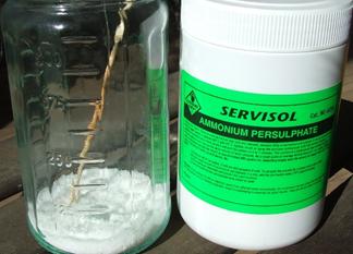
I use Ammonium Persulphate as the etchant which is available from Jaycar etc. This etchant cannot be stored and once mixed up it needs to be used then (environmentally sensitively) disposed of. It also must be quite hot when you use it or it will not work. It is however much quicker, stains clothing less, and doesn’t eat stainless steel as badly if spilled as ferric chloride. I basically do small boards so I tend to mix it up just before use at a ratio of about 40 grams to about 125 mL of recently boiling water. Caution, caution, caution, check the container you are going to do the mixing/etching in to ensure it won’t shatter when you pour the very hot water in. If it is glass, heat it first by rinsing with some warm water to lower the heat shock, then put the powder in, then add the recently boiling water. As far as water temperature I basically bring the water to the boil then carry it outside where I am working and use it. The water would have about 30 seconds to a minute of cooling before I start mixing. The chemical disolves quickly to form a clear liquid, I stir it with a disposable bamboo skewer. Once dissolved the prepared boards are placed carefully in, watching out for splashes. Gentle agitation by just slowly swirling the liquid around is all that is necessary and in under five minutes the boards should be done. You need to keep a carefull eye on the boards as some will etch faster than others, if one board is done before the others then it needs to be removed. Do not leave the boards in the etchant too long as it will start undercutting your fine tracks. In one case where I did this all the letters from the writing on the board were undercut and the toner letters ended up swirling around in the etchant like an alphabet soup. Telling when a board is done is reasonably simple with single sided fibreglass board as holding the board up to the light (easily done if you are outside in the day time) clearly shows the required pattern as the fibreglass substrate is translucent. This is a bit harder with double sided board but again being outside with good light helps.
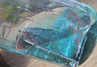
You will note as the copper is etched away that the etchant goes a light blue colour. After etching please dispose of the used etchant carefully in accordance with your local regulations.
If the etchant gets too cold it will not etch, do not be tempted to try and reheat it unless you have a safe way to do this, using the microwave is a bad idea, the stove top is worse. The safest way is just to start again and mix up a new batch.
When removed finally from the etchant the board is immediately washed thoroughly in running water to remove all traces of the etchant. The toner is now removed, again using the green scritchy and metho. At this stage you should have a nice looking board that you can check for breaks in tracks or shorts. Once happy with this I then apply a light coat of PCB lacquer to prevent corrosion and surface discoloration. This gives the boards a professional look and especially if you take a while to get around to using them they will still look good and you will have no problems soldering to them.
Some people leave the lacquer till after drilling but I sometimes take quite a while to get around to this as I often do boards well in advance of when I need them just to have a couple at a time for the etching stage. The PCB lacquer is available in spray cans from places such as Jaycar.
A series of different size drill bits is desirable, you need very fine ones for the small pads for TO39 transistors and similar, slightly larger for IC pads, and larger still for bigger pads to connect to multi-strand hook up wire going off the board. All of these drill bits are well under one milli-meter in diameter and are easily broken. Drill bits are available in packets of miscellaneous sizes from Jaycar etc. A small hand held dremmel or equivalent drill works well for small boards, but for larger quantities or a more professional finish larger shank specialist drill bits as used in commercial PCB processing can be found with some difficulty and these can fit in normal full sized drill presses.
The photo below shows a finished board, showing what is possible with a hand drill.

Happy PCB making.
Paul VK3DIP