A Four Element Six Metre Yagi for 50 to 52.5 MHz
By Paul McMahon VK3DIP
Amateur Radio Magazine Dec 2011 pp 32-40
– Errata and pictures.
This antenna continues to perform well more than 2 years later, and after all that weather the VSWR and performance doesn’t seem to have changed. Obviously it could still fail in the future but so far so good. The major special bits here were the lifting of the driven element to sit on top of the boom (approx. 35mm above the plane of the rest of the antenna) to make construction easier, the use of a capacitive/DC connection between the driven element and the coax, using copper strips for a more reliable connection without weakening the element, and the use of plumbing/water conduit in telescoping sizes as the insulated boom, for cheapness.
Below are the original pictures and figures from the article as well as a couple that didn’t make the original. Hopefully they are a bit easier to see in this format.
73 Paul VK3DIP
Base Design
|
Element |
Length (m) |
Position.(m) |
Diameter.(mm) |
|
1 |
2.902 |
0 |
16 |
|
2 |
2.788 |
1.076 |
16 |
|
3 |
2.636 |
1.769 |
16 |
|
4 |
2.567 |
2.928 |
16 |
Table 1. Base design, position measured from element 1.
At a frequency of 51.0 MHz this gave:
· Input Impedance = 52.74 J 12.76 Ohms
· Forward Gain = 9.4 dBi
· Front-to-Back Ratio = 12.9 dB
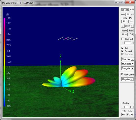
The pattern obtained is shown in Figure 1.
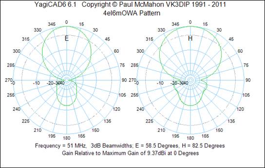
Figure 1/. Antenna Pattern
Along with the overall response in Figure 2/.
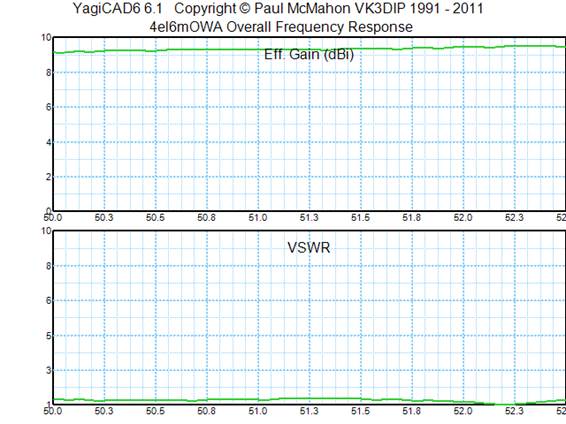
Figure 2/. Overall Response.
To check the effect of displacing the driven element I exported the design to a .nec file and ran the basic single frequency pattern analysis in 4NEC2 . The Non displaced results are shown in Figure 3a, and 3b.
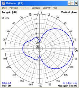
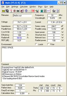
Figure 3a. Base Yagi Far Field Pattern 4NEC2. Figure 3b. Base Yagi main display 4NEC2.
Raising the driven element by 35mm can now be easily done in the 4NEC2 editor and the program re-run. The results for this can be seen in Figures 4a, and 4b.
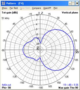
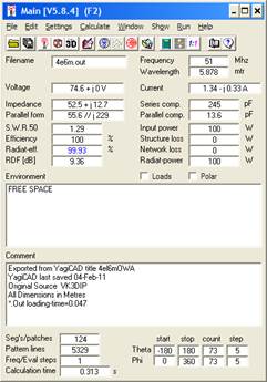
Figure 4a. Modified Yagi Far Field Pattern 4NEC2. Figure 4b. Modified Yagi main display 4NEC2.
Comparison of Figures 3 and 4 shows luckily only very minor differences. The pattern is now slightly asymmetric but the numerical values of input impedance and gain have varied only by the smallest amounts.
For this run I have set the height above ground at 9 metres (because that is about where it will be in my case) and the results are shown in Figures 5a, and 5b.
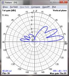
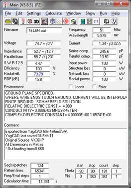
Figure 5a. Modified Yagi, 9 metres above real ground, Far Field Pattern 4NEC2. Figure 5b. Modified Yagi , 9 metres above real ground, main display 4NEC2.
Building it.
Parts List
|
Item |
Description |
Quantity |
Comments |
|
Boom (part1) |
40mm DWV pipe |
3 Metres |
Should fit neatly inside the class 9 |
|
Boom (part2) |
40mm Class 9 pressure pipe |
1.5 Metres |
Eg. Half a 3 metre length, neat fit over 40mm DWV |
|
Glue |
Plumbing pipe glue |
some |
Either red or blue, I used blue. |
|
End Caps |
40mm DWV cap |
2 |
Optional, fit last if required |
|
Elements |
16mm diam. 1mm wall, Al tube. |
4 by 3 Metres |
Cut to lengths given in text |
|
Inspection Tee |
20mm Inspection Tee |
1 |
Eg. Clipsal 246-20 |
|
Hose joiner |
13mm barbed pipe joiner |
1 |
Typical black plastic, cheap irrigation fitting. Check inner diam to fit 10mm fiberglass rod. |
|
Fibreglass Rod |
10mm diam. fibreglass rod |
Approx. 750mm |
Off cut from earlier project originally electric fence support sold in 1 or 1.5M lengths |
|
Conduit |
20mm (gray) electrical conduit |
3 by approx. 75mm |
Off cuts from earlier project. A 5M length is cheapest. Caution, must fit neatly over 16mm Al tube, some do some don’t, so check first. |
|
Shim |
Copper Shim 20mm wide. |
2 by 60mm |
Sold in plastic packet as long life plant labels, or alternately EMC /leadlight tape. |
|
Coax (Tail) |
RG58 |
3 Metres |
Good quality is best |
|
Connector |
N (RG58) Inline female socket |
1 |
Could use PL259 if desired |
|
Balun |
Ferrite tubular cores |
6 |
Jaycar part number LF1258 pkt of 6
|
|
Filler |
Silicon filler etc. |
Lots |
If Silicon get the neutral cure type, much cheaper by the large tube even if you have to buy the gun also. |
|
Bolts |
75mm Quarter inch galvanized bolt nut washer set |
2 |
For mounting the DE to the boom |
|
Epoxy Putty |
5minute Epoxy putty |
Approx. 50mm |
Sold in stick form eg. Selleys KNEAD IT |
Table 2 Parts List
A cross section diagram of the centre of the driven element is shown in figure 7.
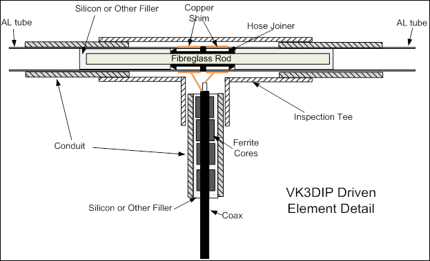
Figure 7. Driven element assembly cross section.
Figures 8 through 14 show the driven element and its components at various stages of construction. One key thing to remember is to always try fitting the pieces together without glue or silicon first, it is a lot easier to adjust spacings or hole diameters with the separate components rather than with bits glued together.
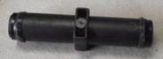
Figure 8. The Hose joiner used as the centre insulator.
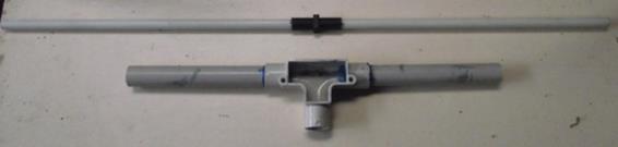
Figure 9. The hose joiner threaded on the fibreglass rod next to the inspection tee.
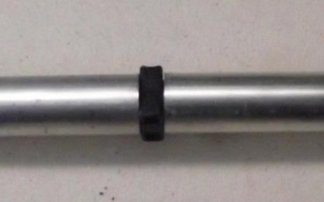
Figure 10. Closeup of DE separator

Figure 11. DE in Inspection tee.
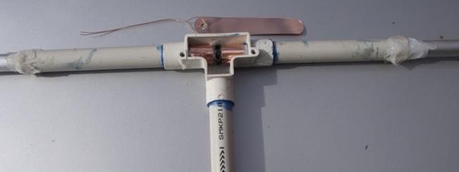
Figure 12a. Copper plant tag shim with driven element.
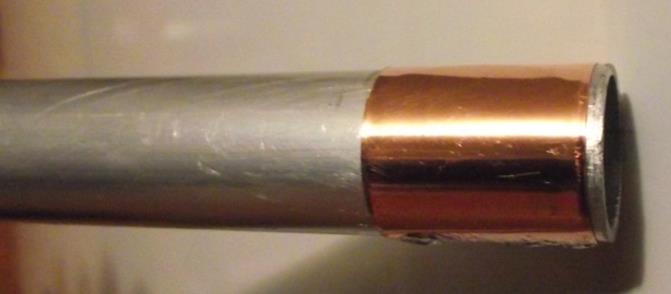
Figure 12b. Copper band on driven element.
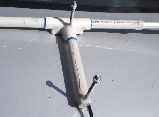
Figure 13. Completed DE bottom view showing mounting bolts
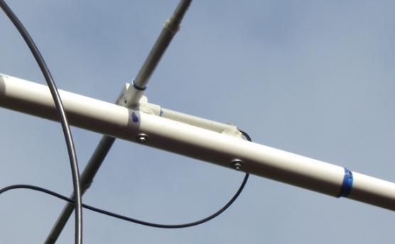
Figure 14. Completed DE mounted on boom, note epoxy putty fillets.
A summary of the completed Yagi configuration is shown in figure 15.
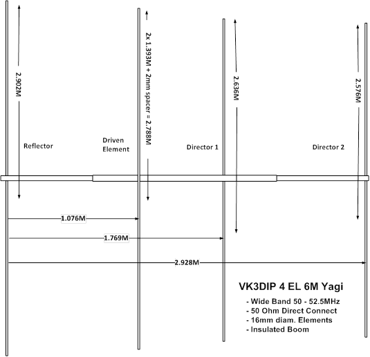
Figure 15. Yagi Summary Diagram.
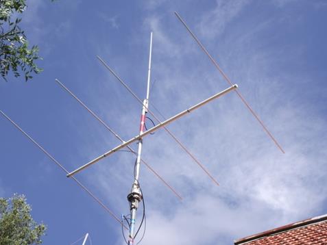
Figure 16. Final Yagi mounted on mast.