The following is based on an article by LB Cebick in QST May 2002 on a Quad Turnstile antenna for 6 Metres. The quad turnstile is basically two full wave loops mounted at right angles fed 90 degrees out of phase to produce an omni-directional horizontally polarized pattern with about 4 dB’s of gain over a dipole. The original article describes exactly how this antenna works etc. so I won’t go into that here, what I will give here is my somewhat simplified construction of a version of it.
The nominal design frequency for this antenna is 50.5MHz but as far as VSWR is concerned my prototype was still under 1.5 to 1 at 53 MHz and 1.2 or better at 50.5 MHz. The pattern is supposedly a little less omni-directional at the higher frequency but is still better than a dipole, and is horizontally polarized so if you are after some 6 Metre DX and you haven’t got the space for a yagi, you won’t suffer from the nominal 20dB polarization loss you would get with some form of vertical.
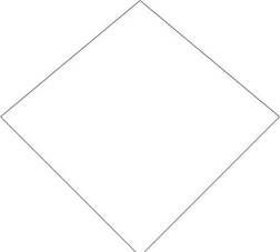
In my case I made the loops out of 6.325 Metre lengths of 16 B&S or about 1.25 mm diameter solid enameled copper wire. According to the original article, I could have used anything from 10 to 18 B&S (or 2.5mm to 1 mm diameter), and the same length would have been fine. The only caveat was to not use plastic coated wire, mainly because this would need an unspecified shorter length. ( I would guess about 5 % if you wanted to give it a go) Each loop is made in the shape of a diamond and is supported on a non-conductive structure made, in my case, out of electrical conduit, which remarkably is actually quite a bit cheaper than wood dowel.
A rough picture of this is shown below.
Two loops like this. Note the break at the bottom where they are feed.
Assembled to look like this..
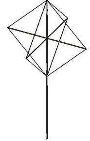
The main pole in my case was a 4 Metre length of 32mm diam conduit and the cross pieces were some thin 10 mm dowel I happened to have had, but thinner conduit with a four way junction box in the centre would have made a neater job of it. Each of the four arms in my case were about 1.1 Metres long but pretty much anything from about 1 to 1.5 Metres would probably do with little effect. Ie. The shape of the loop is not as important as the circumference. To increase the strength of the resultant structure I used some fishing line between the four ends of the spreaders. The two loops were placed through holes drilled in the ends of each of the spreaders and the top of the vertical support.
Feeding the structure is very simple, each loop has an impedance of about 125 Ohms, and needs to be connected by a quarter wave phasing section connected at the base of the diamond. In the original article RG62 was used for this, but as I don’t have any of that I used two pieces of 50 Ohm RG58 in series, the braid connected together at each end and feeding into the two centres, this makes effectively 100 Ohm balanced (and shielded) feeder which is close enough to the nominal loop impedance. Again in my case the velocity factor of the coax was 0.67 so the quarter wave section worked out to be 0,994 Metres long at 50.5 MHz. Another rough drawing, this time of the coax arrangement is shown below.
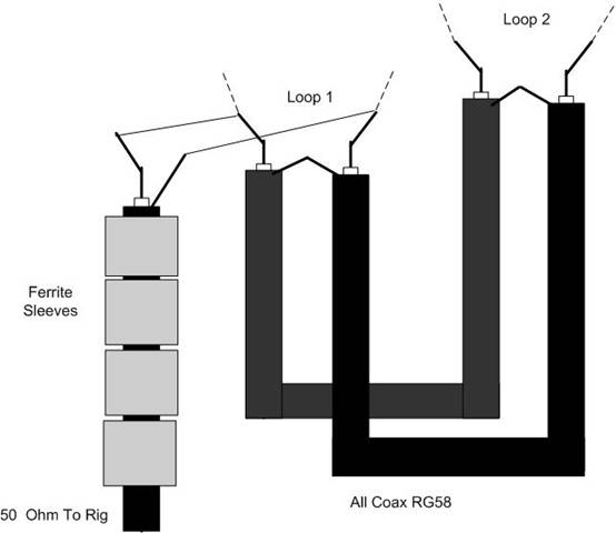
Having the two a bit over 100 Ohm loops connected effectively in parallel via 100 Ohm Feeder gives an effective feed point of around 50 Ohms. So I used some more RG58 cable to connect to the rig. As we are talking about a balanced 50 Ohms in this case I used 6 ferrite sleeves on the end of the coax feeder to act as a choke balun. I used Jaycar part number LF1258 sleeves for this and 6 of them because 6 came in the packet. 6 is a bit of overkill as I had previously tested and found two worked fine at both 2 M and 70cm , but I wanted to be sure in case I subsequently got some more power from somewhere and they are quite cheap. I taped all the coax and sleeves up in insulation tape leaving the four connection points protruding, which were then soldered to the two loops and after pulling the wire loops reasonably taught further taped to the vertical support.
That’s it the whole lot was then stuck up in the air and as previously mentioned the VSWR measured better than 1.2 to 1 at the 50 MHz end going up to 1.5 at the 54 MHz end of the band.
But does it work? Answer yes it does. While tuning down to the bottom end of the band to test the VSWR and going past 50.137 MHz I noticed a strong signal reading well over the S9 on the little meter on my FT690R. Long story short it turned out to be a VK4 talking to a VK3 (the VK4 was by far the stronger signal) and the VK4 subsequently gave me a reasonable signal report when I butted in during a break in the conversation. Not bad for a barefoot 2.5 Watts.
73 Paul. VK3DIP